
Installation: All models of enclosures use similar installation process
All enclosure uses similar squaring methods for models 2, 3, 4, 6, 8, 10 cubic yard dumpsters, either all steel or ceramic laminate and 30 to 40 cubic yard compactor enclosures for setting up the posts and finding square.
Smart Surround requires all pads to be level and square for proper installation for an enclosure. Smart Surround is not liable or responsible for improperly installed pads, which are not level and are not square. Smart surround is not responsible for badly mixed or improperly specified concrete mixtures or poorly installed concrete pads. SmartSurround does have product which can help with a pad which is not level. Please write us for a solutions to your installation difficulties, we are here to help.
Installation of enclosure for 30-40 cubic yard trash compactor
Basic measurements for layout:
- The trash compactor enclosure will set on a pad size 204” x 324”
- The enclosures are 192.645” x 312.36” measured from outside posts
- Gate opening: measured from inside posts is 184.645”
Step 1: On the 204”x324” concrete pad
Step 2: Measure from corner to corner from the 188.645” x 308.036” square on a diagonal line which is 361.211” this proves square.
Step 3: At each corner place post on the intersecting line which will put the post on center.
Step 4: Repeat this on all four corners. Measurement from center to center on the post is 188.645” x 308.036. There are 10 posts with the large compactor enclosure. The measurement from center to center front gate view. Left hand side post 1 to post 2 105.999” post 2 to post 3 105.999” post 3 to post 4 96.039”. Note the two front gate posts can be distinguished by the hinges which should be closest to gate opening. The gate posts center to center measurement is 188.645”. Right hand side post 1 to post 2 is 105.999” post 2 to post 3 is 105.999” post 3 to post 4 is 55.468” post 4 to post 5 is 40.571”. Rear post from end post to center post is 94.323”.
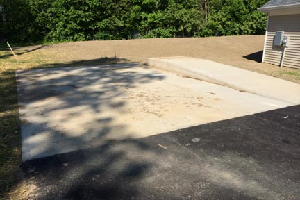
Step 1: Concrete pad
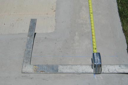
Step 2: Squaring posts
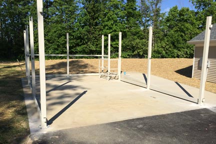
Step 4: 10 posts of large trash compactor enclosure
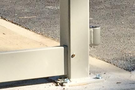
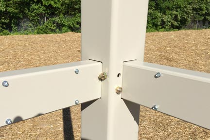
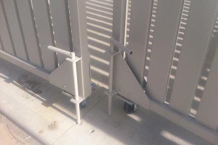
Step 4: Close-up of gate post
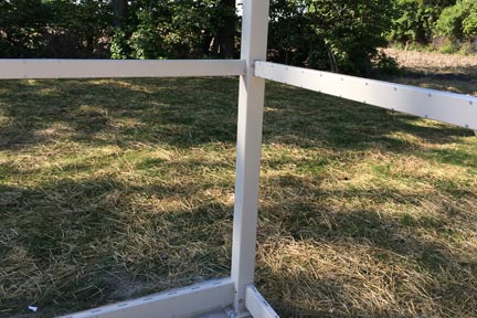
Step 5: Once post is placed on intersecting lines, measure between posts, measurement should be 188.645” from front view.
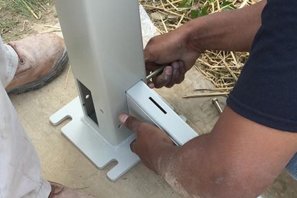
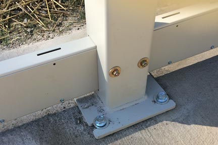
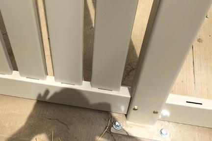
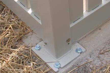
Step 6: As posts are in proper position, drill holes in center of the slotted area, this allows adjustment room. Step 7: Place concrete anchors in each drill hole and tighten within .25” of contact of base plate. This secures the post from falling over, but loose enough to adjust the assembly.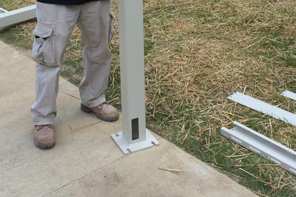
Step 6: Place post in proper position
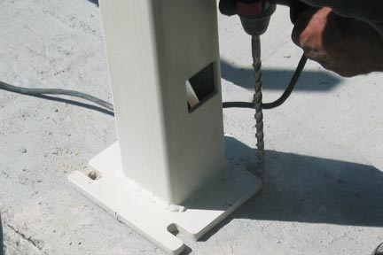
Step 6: Drill holes in center of slotted area on post foot
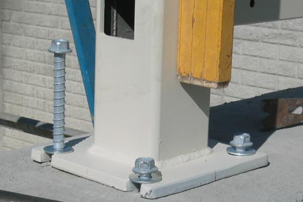
Step 7: Place concrete anchors in each drill hole
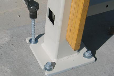
Step 7: Tighten concrete anchors within .25" of contact with baseplate
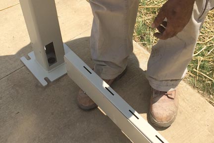
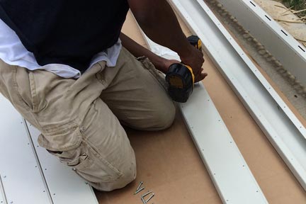
Step 8: Assembly of lower rails, each rail has a cover that matches. The lower rail can easily be identified. It has large drainage openings which face towards the ground. Place cover on rail and put screws on the bottom screw area only. Once this has been achieved slide rail into bottom holes in each tube with the screw cover side is pointing in to the enclosure. Place bolts through the post and through the bottom rail. Once bolts are in place, place nuts and washers on assembly. Don’t tighten bolt until the entire enclosure is assembled. While assembling lower rails, install wheelchair platform railing.
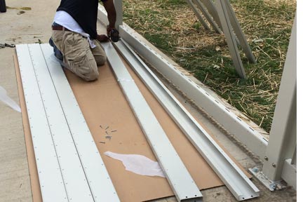
Step 8: Assembly of lower rails, each rail has a cover that matches
Step 8: Place cover on rail
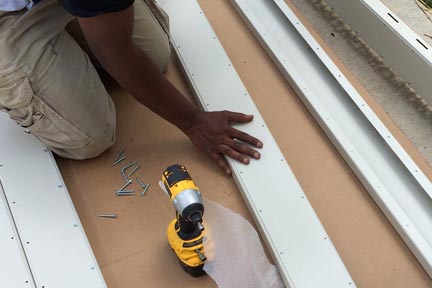
Step 8: Put screw on the bottom area only
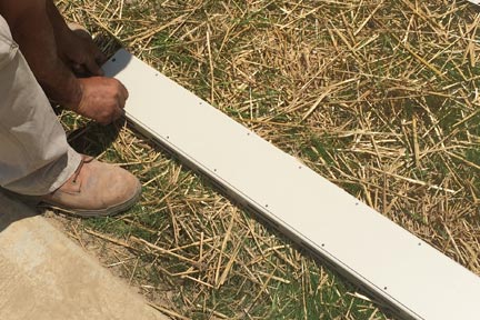
Step 8: Install screws the full length of the rail
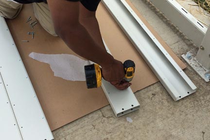
Step 8: Once all screws are installed on the rail, slide rail into bottom holes in each post with the screw cover side pointing into the enclosure
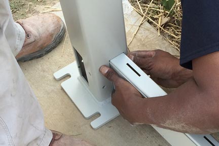
Step 8: Close-up of rail installation into bottom post holes
Step 8: Once bolts are in place, place nuts and washers on assembly
Step 8: Finished assembly of lower rails. Don't tighten bolts until the entire enclosure is assembled
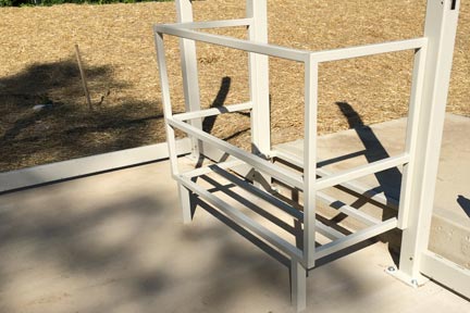
Step 8: While assembling lower rails, install wheelchair platform railing
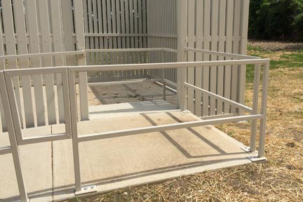
Step 8: Wheelchair platform railing, opening to trash compactor
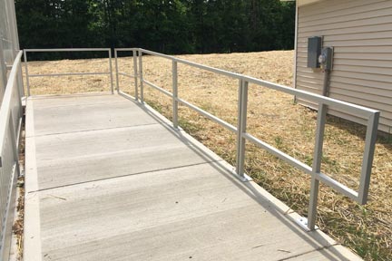
Step 8: Wheelchair ramp railing
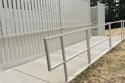
Step 8: Wheelchair ramp railing
Step 9: Assembly of middle rails, each rail has a cover that matches. The middle rail can easily be identified. It smaller than either bottom rail or top rail. Place cover on rail and put screws on both bottom screw area and top area. Once this has been achieved slide rail into middle holes in each post with the screw cover side is pointing into the enclosure. Place bolts through the post and through the middle rail. Once bolts are in place, place nuts and washers on assembly. Don’t tighten bolt until the entire enclosure is assembled.
Step 10: Assembly of top rails, each rail has a cover that matches. The top rail can easily be identified. It has slots openings which face towards the ground. Place cover on rail and put screws on the top screw area only. Once this has been achieved set top rail assembly aside, it will be used later.
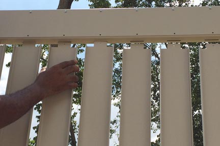
Step 11: Place picket into bottom rail slot and press in, line up hole with hole in middle rail, put self-taping screw in and snug. Do not over tighten. Repeat this process until all pickets are in on one side of enclosure.
Step 9: Assembly of middle rails, are smaller than either bottom rail or top rail, each rail has a cover that matches
Step 9: Place cover on rail, Install screws the full length of the rail
Step 9: Once this has been achieved slide rail into middle holes in each post with the screw cover side is pointing into the enclosure
Step 9: Place bolts through the post and through the middle rail. Once bolts are in place, place nuts and washers on assembly. Don’t tighten bolts until the entire enclosure is assembled
Step 10: Assembly of top rails, each rail has a cover that matches. Place cover on rail and put screws on the top screw area only
Step 11: Place picket into bottom rail slot and press in, line up hole with hole in middle rail, put self-taping screw in and snug
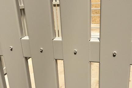
Step 11: Line up hole with hole in middle rail, put self-taping screw in and snug. Do not over tighten
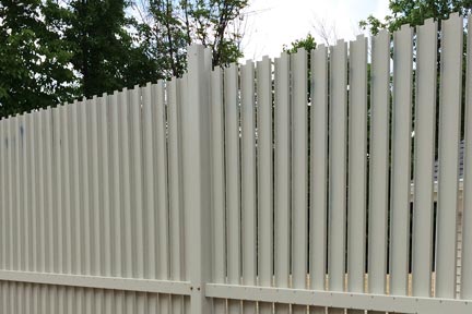
Step 11: Repeat this process until all pickets are in on one side of enclosure
Step 12: Install top rail; the top of post has open slots to install top rail. Starting at one end gently slide picket end into top rail. Review all pickets before installing bolts or screws into top rail. Once all pickets are installed into top rail, install post bolts on top rail. Do not tighten bolts.
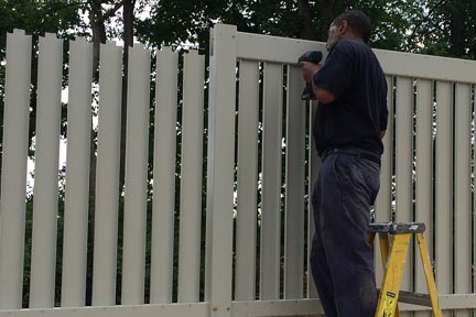
Step 13: install picket self-tapping screws on bottom rail first, do not over tightened, just snug. Next install self-tapping screws on top rail for pickets.
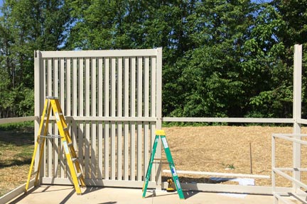
Step 14: Repeat the process on the remaining walls.
Step 15: At this point all the walls are assembled, place post end cap on by tapping lightly with rubber hammer or by hand.
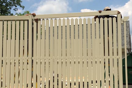
Step 12: Install top rail; the top of post has open slots to install top rail.
Step 12: Starting at one end gently slide picket end into top rail.
Step 12: Once all pickets are installed into top rail, install post bolts on top rail. Do not tighten bolts.
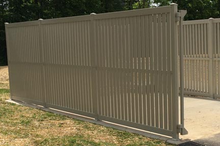
Step 15: At this point all the walls are assembled, place post end cap on by tapping lightly with rubber hammer or by hand.
Step 16: After all post caps have been installed tighten all the bolts on the post. Do not over tighten. If you tighten bolts before you place post caps on, they will not fit. The cap has a friction fit designed to get tight by tightening post bolts.
Step 17: Place gate hinge section on post pins. (side frame 7.2) Note: there is a ball bearing which must be placed in each hinge with light grease. After achieving hinge section installation repeat procedure to opposing hinge section.
Step 18: Place bottom frame #4 into side frame and install bolts. Place side frame 7.1 which has cane bolt support on it, to bottom frame and bolt it.
Step 19: Assemble center frame to center frame cover using self-taping screw. Assemble using step 8. Once the center frame is assembled install the frame with screw side facing toward the inside of the enclosure. Bolt in place on both ends.
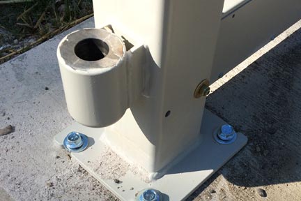
Step 17: Place gate hinge section on post pins.
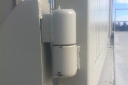
Step 17: Note: there is a ball bearing which must be placed in each hinge with light grease.

Step 18: Place bottom frame #4 into side frame and install bolts.
Step 18: Place side frame 7.1 which has cane bolt support on it, to bottom frame and bolt it.
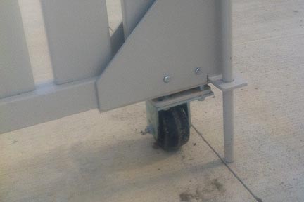
Step 20: Place picket into bottom rail slot and press in, line up hole with hole in middle rail, put self-taping screw in and snug. Do not over tighten. Repeat this process until all pickets are in place. Follow Step 11-Step 12. Tighten all bolts and adjust until level. If your unit come with wheel support it will act as self-leveling if the pad is level. Repeat the same process on opposing gate assembly.
Step 21: After both gates are installed and all bolts and concrete fasteners are tightened, line gates so they are square to the enclosure. Place a cane bolt in support and let it rest on the pad. With a construction pencil draw around the cane bolt. Repeat this on the opposing gate. Remove cane bolts and open gate. Using a .75" or large hammer bit drill, drill a hole 4’’ to 5” deep. Ream hole out to loosen tolerance. This will allow the cane bolt to easily enter the hole.
Step 21: After both gates are installed, tighten all bolts and concrete fasteners.
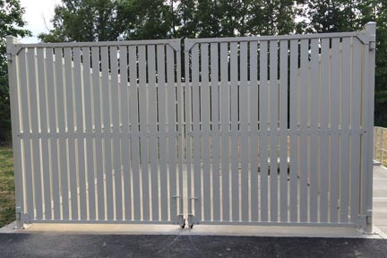
Step 21: Line gates so they are square to the enclosure. Place a cane bolt in support and let it rest on the pad. With a construction pencil draw around the cane bolt. Repeat this on the opposing gate.
Step 21: Remove cane bolts and open gate. Using a 0.75" or large hammer drill bit, drill a hole 4" to 5” deep. Ream hole out to loosen tolerance. This will allow the cane bolt to easily enter the hole.
Installation of enclosure for 10 cubic yard dumpster
- General info: This installation is for the all steel dumpster enclosures. The enclosure will handle a 10 cubic yard dumpster
- Review photos showing installation
- Basic measurements for layout
- The dumpster enclosure will set on a Pad size 130” x 130”
- The enclosures are 120” x 120” measured from outside post
- Measuring from center of post makes a square 116” x 116”
- Gate opening; measured from inside posts is 112”
Step 1: On the 130” x 130” concrete pad snap string a square 116”x116” which is 7” from the side of the pad.
Step 2: Measure from corner to corner from the 116”x116” square on a diagonal line which is 164.049” this proves square.
Step 3: At each corner place post on the intersecting line which will put the post on center.
Step 4: Repeat this on all four corners. Note the two front gate posts can be distinguished by the hinges which should be closest to gate opening.
Step 5: Once post is placed on intersecting lines, measure between posts, measurement should be 112”.
Step 6: As post are in proper position drill holes’ in center of the slotted area, this allows adjustment room.
Step 7: Place concrete anchors in each drill hole and tighten within .25” of contact of base plate. This secures the post from falling over but loses enough to adjust the assemble.
Step 8: Assembly of lower rails, each rail has a cover that matches. The lower rail can easily be identified. It has large drainage openings which face towards the ground. Place cover on rail and put screws on the bottom screw area only. Once this has been achieved slide rail into bottom holes in each tube with the screw cover side is pointing in to the enclosure. Place bolts through the post and through the bottom rail. Once bolts are in place, place nuts and washers on assembly. Don’t tighten bolt until the entire enclosure is assembled.
Step 9: Assembly of middle rails, each rail has a cover that matches. The middle rail can easily be identified. It smaller then either bottom rail or top rail. Place cover on rail and put screws on both bottom screw area and top area. Once this has been achieved slide rail into middle holes in each tube with the screw cover side is pointing in to the enclosure. Place bolts through the post and through the middle rail. Once bolts are in place, place nuts and washers on assembly. Don’t tighten bolt until the entire enclosure is assembled.
Step 10: Assembly of top rails, each rail has a cover that matches. The top rail can easily be identified. It has slots openings which face towards the ground. Place cover on rail and put screws on the top screw area only. Once this has been achieved set top rail assembly aside, it will be used later.
Step 11: Place picket into bottom rail slot and press in, line up hole with hole in middle rail, put self-taping screw in and snug. Do not over tighten. Repeat this process until all pickets are in on one side of enclosure.
Step 12: Install top rail; the top of post has open slots to install top rail. Starting at one end gently slide picket end into top rail. Once you have all pickets installed into top rail, review before installing bolts or screws. If all pickets are installed into top rail, install post bolts on top rail. Do not tighten bolts.
Step 13: install picket self-tapping screws on bottom rail first, do not over tightened, just snug. Next install self-tapping screws on top rail for pickets.
Step 14: Repeat the process on the remaining two walls.
Step 15: At this point all the walls are assembled, place post end cap on by tapping lightly with rubber hammer or by hand.
Step 16: After all post caps have been installed tighten all the bolts on the post. Do not over tighten. If you tighten bolts before you place post caps on the post cap will not fit. The reason for this by design, the cap has a friction fit designed to get tight by tightening post bolts.
Step 17: Place gate hinge section on post pins. (side frame 7.2) Note: there is a ball bearing which must be placed in each hinge with light grease. After achieving hinge section installation repeat procedure to opposing hinge section.
Step 18: Place bottom frame #4 into side frame and install bolts. Place side frame 7.1 which has caine bolt support on it, to bottom frame and bolt it.
Step 19: assemble center frame to center frame cover using self-taping screw. Assemble using step 8. Once the center frame is assembled install the frame with screw side facing toward the inside of the enclosure. Bolt in place on both ends.
Step 20: Place picket into bottom rail slot and press in, line up hole with hole in middle rail, put self-taping screw in and snug. Do not over tighten. Repeat this process until all pickets are in place. Follow Steps 11 and 12. Tighten all bolts and adjust until level. If your unit comes with wheel support, it will act as self-leveling if the pad is level. Repeat the same process on opposing gate assembly.
Step 21: After both gates are installed and all bolts and concrete fasteners are tightened, line gates so they are square to the enclosure. Place a cane bolt in support and let it rest on the pad. With a construction pencil draw around the cane bolt. Repeat this on the opposing gate. Remove cane bolts and open gate. Using a .75 or large hammer bit drill, drill a hole 4" to 5” deep. Ream hole out to loosen tolerance. This will allow the cane bolt to easily enter the hole.
Changes in design and specification can take place without notification to you.
SmartSurround LLC Limited Warranty
What is covered:
This limited warranty covers defects in materials and workmanship in the product.
What is not covered:
This Limited warranty does not cover any damage, or malfunction resulting from any alteration or modification, improper or unreasonable use of the product, included are: maintenance, abuse, accidents, exposure or excess moisture, fire. Improper packaging, shipping. Scratches and dents with custom or modified assemblies and are not warranted.
This limited warranty does not cover any damage, distortion or malfunction resulting from installation or removal of the product from any installation. Any unauthorized tampering with the product, any repairs attempted by anyone unauthorized by SmartSurround to make such repairs or any other costs which does not relate directly to a defect in material and or workmanship of the product. This limited warranty does not cover cartons, equipment, or accessories used in conjunction with the product. with limitations any other exclusions here in SmartSurround does not warrant that the product covered here by including without limitations the technology or integration included in the product will not become obsolete or that the items or will remain compatible with other products and technologies which the product may be used. Dents scratches and other surface aberrations which are caused due to shipping and handling and installation are not warranted. No guarantee on color fade or color matching is warranted. SmartSurround does not cover labor, installation or shipping and contractual obligations are not warranted.
How long this coverage lasts: The standard limited warranty for SmartSurround products is one year from the date of the completion of the production of the product. It is only warranted to cover materials which will meet the ASTM standard 500 for steel and the powder coating which will be free of cracks or peeling for a period of one year.
If material is found defective; the part in question may be sent back to SmartSurround at the owners expense and a replacement part or the part in question may be re manufactured.
